QUESTION IMAGE
Question
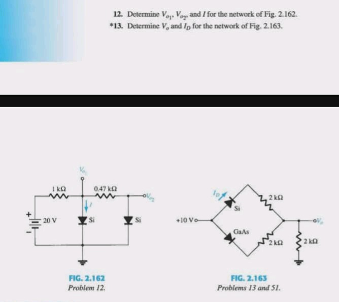
- determine ( v_{o_1}, v_{o_2} ), and ( i ) for the network of fig. 2.162.
*13. determine ( v_o ) and ( i_d ) for the network of fig. 2.163.
fig. 2.162
problem 12.
fig. 2.163
problems 13 and 51.
Problem 12 (Fig. 2.162)
We analyze the diode circuit. For a silicon diode, the forward voltage drop \( V_D \approx 0.7 \, \text{V} \).
Step 1: Analyze the left diode (connected to ground)
The left diode is forward - biased? Let's check the voltage across it. The source is \( 20 \, \text{V} \), and the resistor is \( 1 \, \text{k}\Omega \). But the diode is connected between the node \( V_{o1} \) and ground. If the diode is forward - biased, \( V_{o1}= 0.7 \, \text{V} \) (since it's a silicon diode forward - biased, anode at \( V_{o1} \), cathode at ground). Wait, let's check the current path. The current \( I \) flows from the \( 20 \, \text{V} \) source, through the \( 1 \, \text{k}\Omega \) resistor, through the diode (if forward - biased) to ground. But also, there is a \( 0.47 \, \text{k}\Omega \) resistor and another diode. Wait, the second diode: its cathode is at \( V_{o2} \) and anode? Wait, the second diode is connected with cathode at \( V_{o2} \) and anode? Wait, no, the diagram shows two silicon diodes. The left diode: anode at \( V_{o1} \), cathode at ground. The right diode: anode? Wait, no, the right diode is connected with cathode at \( V_{o2} \) and what? Wait, the left diode is between \( V_{o1} \) (anode) and ground (cathode). The right diode is between \( V_{o2} \) (cathode) and the node between \( 0.47 \, \text{k}\Omega \) and \( V_{o1} \)? Wait, maybe I misread the diagram. Let's re - draw mentally: The circuit has a \( 20 \, \text{V} \) source (+ terminal) connected to a \( 1 \, \text{k}\Omega \) resistor, then to a node \( V_{o1} \). From \( V_{o1} \), a silicon diode (anode at \( V_{o1} \), cathode at ground) is connected. Also, from \( V_{o1} \), a \( 0.47 \, \text{k}\Omega \) resistor is connected to \( V_{o2} \), and from \( V_{o2} \), a silicon diode (cathode at \( V_{o2} \), anode? Wait, no, the second diode: if it's a silicon diode, and assuming it's reverse - biased? Wait, no, let's think again.
Wait, the left diode: forward - biased. So \( V_{o1}=0.7 \, \text{V} \) (forward voltage drop of silicon diode). Now, the current \( I \) through the \( 1 \, \text{k}\Omega \) resistor: \( I=\frac{20 - 0.7}{1\times10^{3}}=\frac{19.3}{1000}=19.3 \, \text{mA} \)? Wait, no, that can't be right because there is another branch. Wait, no, the second diode: the right diode. Let's check the voltage at \( V_{o2} \). The right diode: its anode is at the node between \( 0.47 \, \text{k}\Omega \) and \( V_{o1} \)? Wait, no, the right diode is connected with cathode at \( V_{o2} \) and anode at the node between \( 0.47 \, \text{k}\Omega \) and \( V_{o1} \)? Wait, no, the right diode is reverse - biased. Because the voltage at \( V_{o1} \) is \( 0.7 \, \text{V} \), and the right diode's cathode is at \( V_{o2} \), and if we assume the right diode is reverse - biased, then no current flows through the \( 0.47 \, \text{k}\Omega \) resistor and the right diode. So the current \( I \) is through the left diode.
So, \( V_{o1} = 0.7 \, \text{V} \) (forward - biased silicon diode, anode at \( V_{o1} \), cathode at ground).
The current \( I \): Using Ohm's law, \( I=\frac{20 - 0.7}{1\times10^{3}}=\frac{19.3}{1000}=19.3 \, \text{mA} \)? Wait, no, that's wrong. Wait, the left diode is between \( V_{o1} \) and ground. So the voltage across the \( 1 \, \text{k}\Omega \) resistor is \( V = 20 - 0.7=19.3 \, \text{V} \), so \( I=\frac{19.3}{1\times10^{3}} = 19.3 \, \text{mA} \)? But wait, the right diode: is it reverse - biased? Let's check the voltage at \( V_{o2} \). Since no current flows through the \( 0.47 \, \text{k}\Omega \) resistor (because the r…
We have a diode bridge with a silicon diode (Si) and a gallium - arsenide diode (GaAs). The forward voltage drop for a silicon diode \( V_{Si}\approx0.7 \, \text{V} \), and for a gallium - arsenide diode \( V_{GaAs}\approx1.2 \, \text{V} \) (forward voltage drop).
Step 1: Analyze the diodes
The top diode is a silicon diode (Si) with anode at \( + 10 \, \text{V} \), cathode at the top of the \( 2 \, \text{k}\Omega \) resistor. The bottom diode is a GaAs diode with anode at the bottom of the lower \( 2 \, \text{k}\Omega \) resistor and cathode at \( + 10 \, \text{V} \)? Wait, no, the bridge: \( + 10 \, \text{V} \) is connected to the top of the Si diode and the bottom of the GaAs diode. The Si diode: anode at \( + 10 \, \text{V} \), cathode at the node connected to the top \( 2 \, \text{k}\Omega \) resistor and the output \( V_o \) branch. The GaAs diode: anode at the node connected to the bottom \( 2 \, \text{k}\Omega \) resistor and the output \( V_o \) branch, cathode at \( + 10 \, \text{V} \).
Let's find the voltage at the two nodes of the bridge (excluding the output branch). Let the top node of the bridge (connected to Si diode's cathode) be \( V_1 \), and the bottom node (connected to GaAs diode's anode) be \( V_2 \).
For the Si diode: if forward - biased, \( V_{Si}=V(anode)-V(cathode)=10 - V_1 = 0.7 \, \text{V}\Rightarrow V_1 = 10 - 0.7=9.3 \, \text{V} \)
For the GaAs diode: if forward - biased, \( V_{GaAs}=V(cathode)-V(anode)=10 - V_2 = 1.2 \, \text{V}\Rightarrow V_2 = 10 - 1.2 = 8.8 \, \text{V} \)
Now, the two \( 2 \, \text{k}\Omega \) resistors in the bridge: the voltage across the top \( 2 \, \text{k}\Omega \) resistor is \( V_1 - V_o \), and across the bottom \( 2 \, \text{k}\Omega \) resistor is \( V_2 - V_o \). Also, the output branch has a \( 2 \, \text{k}\Omega \) resistor to ground.
Wait, maybe a better approach: Assume the diodes are forward - biased. The Si diode has a lower forward voltage drop than the GaAs diode. Wait, no, GaAs diodes have a higher forward voltage drop (around 1.2 V) compared to Si (0.7 V).
The current through the Si diode: Let's consider the paths. The top branch: \( + 10 \, \text{V}
ightarrow \text{Si diode}
ightarrow \text{top } 2 \, \text{k}\Omega
ightarrow V_o
ightarrow 2 \, \text{k}\Omega
ightarrow \text{ground} \)
The bottom branch: \( + 10 \, \text{V}
ightarrow \text{bottom } 2 \, \text{k}\Omega
ightarrow \text{GaAs diode}
ightarrow V_o
ightarrow 2 \, \text{k}\Omega
ightarrow \text{ground} \)
Wait, no, the GaAs diode's cathode is at \( + 10 \, \text{V} \), so current through GaAs diode would flow from \( V_2 \) (anode) to \( + 10 \, \text{V} \) (cathode) if \( V_2>10 - 1.2 = 8.8 \, \text{V} \). The Si diode's current flows from \( + 10 \, \text{V} \) (anode) to \( V_1 \) (cathode) if \( V_1<10 - 0.7 = 9.3 \, \text{V} \)
Let's use Kirchhoff's laws. Let the current through the top \( 2 \, \text{k}\Omega \) resistor be \( I_1 \), through the bottom \( 2 \, \text{k}\Omega \) resistor be \( I_2 \), and through the output \( 2 \, \text{k}\Omega \) resistor be \( I_o=\frac{V_o}{2\times10^{3}} \)
We know that \( I_1 - I_2=I_o \)
For the Si diode: \( 10 - V_1 = 0.7\Rightarrow V_1 = 9.3 \, \text{V} \), and \( V_1=V_o + I_1\times2\times10^{3} \)
For the GaAs diode: \( V_2 - 10 = 1.2\Rightarrow V_2 = 11.2 \, \text{V} \)? No, that can't be, because the source is

Snap & solve any problem in the app
Get step-by-step solutions on Sovi AI
Photo-based solutions with guided steps
Explore more problems and detailed explanations
We have a diode bridge with a silicon diode (Si) and a gallium - arsenide diode (GaAs). The forward voltage drop for a silicon diode \( V_{Si}\approx0.7 \, \text{V} \), and for a gallium - arsenide diode \( V_{GaAs}\approx1.2 \, \text{V} \) (forward voltage drop).
Step 1: Analyze the diodes
The top diode is a silicon diode (Si) with anode at \( + 10 \, \text{V} \), cathode at the top of the \( 2 \, \text{k}\Omega \) resistor. The bottom diode is a GaAs diode with anode at the bottom of the lower \( 2 \, \text{k}\Omega \) resistor and cathode at \( + 10 \, \text{V} \)? Wait, no, the bridge: \( + 10 \, \text{V} \) is connected to the top of the Si diode and the bottom of the GaAs diode. The Si diode: anode at \( + 10 \, \text{V} \), cathode at the node connected to the top \( 2 \, \text{k}\Omega \) resistor and the output \( V_o \) branch. The GaAs diode: anode at the node connected to the bottom \( 2 \, \text{k}\Omega \) resistor and the output \( V_o \) branch, cathode at \( + 10 \, \text{V} \).
Let's find the voltage at the two nodes of the bridge (excluding the output branch). Let the top node of the bridge (connected to Si diode's cathode) be \( V_1 \), and the bottom node (connected to GaAs diode's anode) be \( V_2 \).
For the Si diode: if forward - biased, \( V_{Si}=V(anode)-V(cathode)=10 - V_1 = 0.7 \, \text{V}\Rightarrow V_1 = 10 - 0.7=9.3 \, \text{V} \)
For the GaAs diode: if forward - biased, \( V_{GaAs}=V(cathode)-V(anode)=10 - V_2 = 1.2 \, \text{V}\Rightarrow V_2 = 10 - 1.2 = 8.8 \, \text{V} \)
Now, the two \( 2 \, \text{k}\Omega \) resistors in the bridge: the voltage across the top \( 2 \, \text{k}\Omega \) resistor is \( V_1 - V_o \), and across the bottom \( 2 \, \text{k}\Omega \) resistor is \( V_2 - V_o \). Also, the output branch has a \( 2 \, \text{k}\Omega \) resistor to ground.
Wait, maybe a better approach: Assume the diodes are forward - biased. The Si diode has a lower forward voltage drop than the GaAs diode. Wait, no, GaAs diodes have a higher forward voltage drop (around 1.2 V) compared to Si (0.7 V).
The current through the Si diode: Let's consider the paths. The top branch: \( + 10 \, \text{V}
ightarrow \text{Si diode}
ightarrow \text{top } 2 \, \text{k}\Omega
ightarrow V_o
ightarrow 2 \, \text{k}\Omega
ightarrow \text{ground} \)
The bottom branch: \( + 10 \, \text{V}
ightarrow \text{bottom } 2 \, \text{k}\Omega
ightarrow \text{GaAs diode}
ightarrow V_o
ightarrow 2 \, \text{k}\Omega
ightarrow \text{ground} \)
Wait, no, the GaAs diode's cathode is at \( + 10 \, \text{V} \), so current through GaAs diode would flow from \( V_2 \) (anode) to \( + 10 \, \text{V} \) (cathode) if \( V_2>10 - 1.2 = 8.8 \, \text{V} \). The Si diode's current flows from \( + 10 \, \text{V} \) (anode) to \( V_1 \) (cathode) if \( V_1<10 - 0.7 = 9.3 \, \text{V} \)
Let's use Kirchhoff's laws. Let the current through the top \( 2 \, \text{k}\Omega \) resistor be \( I_1 \), through the bottom \( 2 \, \text{k}\Omega \) resistor be \( I_2 \), and through the output \( 2 \, \text{k}\Omega \) resistor be \( I_o=\frac{V_o}{2\times10^{3}} \)
We know that \( I_1 - I_2=I_o \)
For the Si diode: \( 10 - V_1 = 0.7\Rightarrow V_1 = 9.3 \, \text{V} \), and \( V_1=V_o + I_1\times2\times10^{3} \)
For the GaAs diode: \( V_2 - 10 = 1.2\Rightarrow V_2 = 11.2 \, \text{V} \)? No, that can't be, because the source is