QUESTION IMAGE
Question
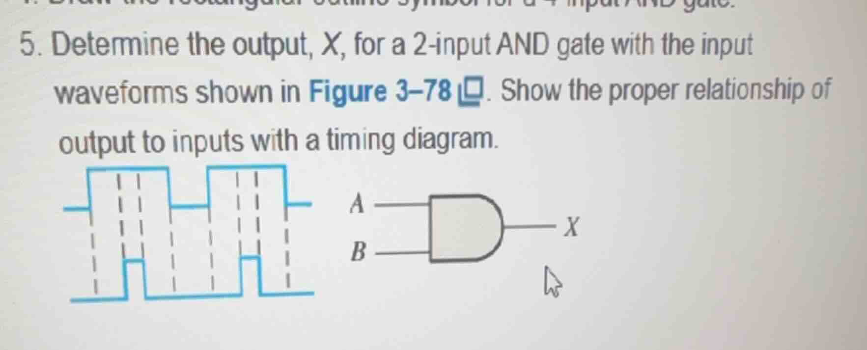
- determine the output, x, for a 2 - input and gate with the input waveforms shown in figure 3 - 78. show the proper relationship of output to inputs with a timing diagram.
Step1: Recall AND gate logic
The output of an AND gate is defined as \(X = A \cdot B\) (or \(X = A \land B\)), where \(X=1\) only if both \(A=1\) and \(B=1\); else \(X=0\).
Step2: Compare input waveforms
Align the two input waveforms by time intervals. For each interval, check if both \(A\) and \(B\) are high.
Step3: Generate output waveform
For each time interval:
- If \(A=1\) and \(B=1\), set \(X=1\)
- If either \(A=0\) or \(B=0\), set \(X=0\)
Step4: Plot timing diagram
Align the output waveform \(X\) vertically with the input waveforms, matching the time intervals from Step 2.

Snap & solve any problem in the app
Get step-by-step solutions on Sovi AI
Photo-based solutions with guided steps
Explore more problems and detailed explanations
The output waveform \(X\) is high (1) only during the time intervals where both input waveforms \(A\) and \(B\) are high (1), and low (0) at all other times. The timing diagram below illustrates this:
| Time Interval | Input \(A\) | Input \(B\) | Output \(X = A \cdot B\) |
|---|---|---|---|
| 2 | 1 | 1 | 1 |
| 3 | 0 | 1 | 0 |
| 4 | 0 | 0 | 0 |
| 5 | 1 | 0 | 0 |
| 6 | 1 | 1 | 1 |
| 7 | 0 | 1 | 0 |
| 8 | 0 | 0 | 0 |
Visual timing diagram alignment:
- \(A\): High → High → Low → Low → High → High → Low → Low
- \(B\): Low → High → High → Low → Low → High → High → Low
- \(X\): Low → High → Low → Low → Low → High → Low → Low