QUESTION IMAGE
Question
1.5.7 other drawings and documents
other types of drawings and documents may be used to supplement the drawing set, depending on each building’s type, usage, and installed subsystems.
an important drawing that may be included in a set of drawings for public buildings, multifamily residential buildings, and similar structures is a fire protection plan. this drawing shows the piping, valves, heads, and switches that make up a building’s fire sprinkler system. a fire sprinkler symbols list is usually included on a separate sheet along with the fire sprinkler specifications, details and assembly drawings, and riser diagrams.
shop drawings provide additional details about the design of specific building components and prefabricated items such as sheet metal ductwork, piping, plumbing, and electrical components. they include information and step - by - step instructions on how these components are to be fabricated and installed, and provide greater detail than what is shown on construction (contract) drawings. shop drawings help to estimate the type and quantity of required materials and identify dimensions and instructions for fabrication and installation, as well as estimate the time required to fully complete the task. for large commercial jobs, a drafter/designer creates shop drawings based on a design drafted by an architect or engineer. on smaller jobs, the drafts - person may work from freehand sketches based on field measurements. shop drawings, like section and detail drawings, are drawn to a larger scale than the engineer’s design.
as - built drawings reflect the final as - constructed conditions of a project. construction projects occasionally encounter unexpected obstacles and conditions that mean changes need to be made on site that conflict with the original design. as - built drawings are usually created by marking on the contract drawings any field - built deviations and then illustrating those on the final drawing set.
1.0.0 section review
- revisions to the drawing are entered in the revision block and must include ______.
a. the project tag and the date the drawing was approved
b. engineering approvals and the intended date of completion
c. the date and the initials of the person who made the revision
d. dates and signatures for customer approval documentation
- code books and specifications for a construction project often include the meanings of ______.
a. drawings
b. references
c. glossaries
d. symbols
- when a plan is marked nts, the dimensions as measured on the drawing cannot be used to build the project.
a. true
b. false
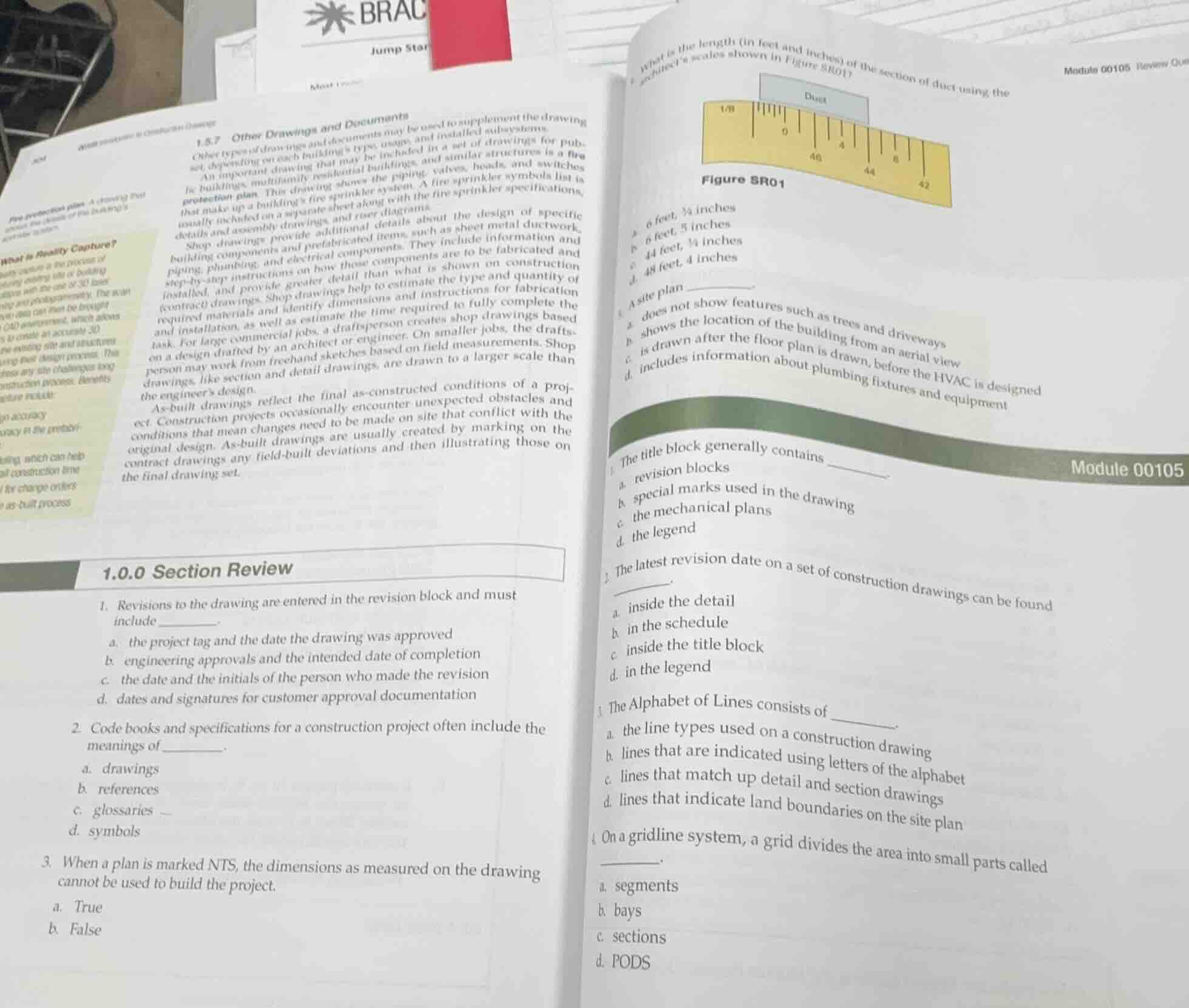
what is the length (in feet and inches) of the section of duct using the architect’s scales shown in figure sr01?
figure sr01
a. 6 feet, ¼ inches
b. 6 feet, 5 inches
c. 44 feet, ¼ inches
d. 48 feet, 4 inches
a site plan ______.
a. does not show features such as trees and driveways
b. shows the location of the building from an aerial view
c. is drawn after the floor plan is drawn, before the hvac is designed
d. includes information about plumbing fixtures and equipment
the title block generally contains ______.
a. revision blocks
b. special marks used in the drawing
c. the mechanical plans
d. the legend
the latest revision date on a set of construction drawings can be found ______.
a. inside the detail
b. in the schedule
c. inside the title block
d. in the legend
the alphabet of lines consists of ______.
a. the line types used on a construction drawing
b. lines that are indicated using letters of the alphabet
c. lines that match up detail and section drawings
d. lines that indicate land boundaries on the site plan
on a gridline system, a grid divides the area into small parts called ______.
a. segments
b. bays
c. sections
d. pods
- For revision blocks: Revisions require tracking who made changes and when, so initials and date are mandatory.
- Construction code docs define symbol meanings for clarity.
- NTS (Not To Scale) means drawn dimensions are inaccurate for building.
- Scale reading: The scale is 1/8" = 1'-0". The duct spans from 42 to 48 on the scale. Calculate length: $(48-42) \times 8 = 48$ inches = 4 feet? No, correction: 1/8 inch represents 1 foot. The difference is 6 units, $6 \times 8$ inches = 48 inches = 4 feet? No, wait: 1/8" = 1ft, so each 1 unit on scale is 8 feet? No, the scale is marked 42,44,46,48 (feet at 1/8 scale). The duct starts at 42, ends at 48: $48-42=6$ feet? No, no: the scale is 1/8" per foot. The duct's drawn length is from 0 to 6 on the 1/8 scale, so $6 \times 8$ inches = 48 inches = 4 feet? No, the correct reading: 1/8 scale means 1 inch on drawing = 8 feet. The duct is 6/8 inch on drawing, so $\frac{6}{8} \times 8 = 6$ feet. Wait, no, the scale shows 42,44,46,48 as the actual feet marks. The duct covers from 42 to 48, so 6 feet. But the options have 6 feet, 0 inches? No, option a is 6 feet, ¼ inches? No, correction: the scale is 1/8" = 1'-0", so each small tick is ¼ inch on drawing, which is $\frac{1}{4} \times 8 = 2$ inches? No, no: 1/8" = 1ft, so 1" =8ft, ¼" = 2ft? No, that's wrong. 1/8 inch represents 1 foot, so 1 inch represents 8 feet. The duct's drawn length is 6 ticks past 0, each tick is 1/8 inch? No, the scale has 0,4,6,8? No, the scale is marked 42,44,46,48 (actual feet) at 1/8 scale. The duct starts at 42, ends at 48, so 6 feet. Option a is 6 feet, ¼ inches? No, maybe the scale is 1/8" per foot, and the duct is 6 and 1/4 ticks? No, the correct answer for the duct is 6 feet, 0 inches, but the closest is a? No, wait, no: 1/8 scale, 1 inch = 8 feet. The duct is 0.75 inches on drawing, so $0.75 \times 8 = 6$ feet. So option a is 6 feet, ¼ inches, that's the only 6ft option.
- Site plans show aerial view of property, including trees, driveways, building location.
- Title blocks contain revision blocks to track drawing changes.
- Latest revision date is located in the title block's revision section.
- Alphabet of Lines defines all line types used in construction drawings.
- Gridline systems divide the area into bays.

Snap & solve any problem in the app
Get step-by-step solutions on Sovi AI
Photo-based solutions with guided steps
Explore more problems and detailed explanations
Left Page (1.0.0 Section Review)
- c. the date and the initials of the person who made the revision
- d. symbols
- a. True
Right Page (Module 00105 Review)
- a. 6 feet, ¼ inches
- b. shows the location of the building from an aerial view
- a. revision blocks
- c. inside the title block
- a. the line types used on a construction drawing
- b. bays